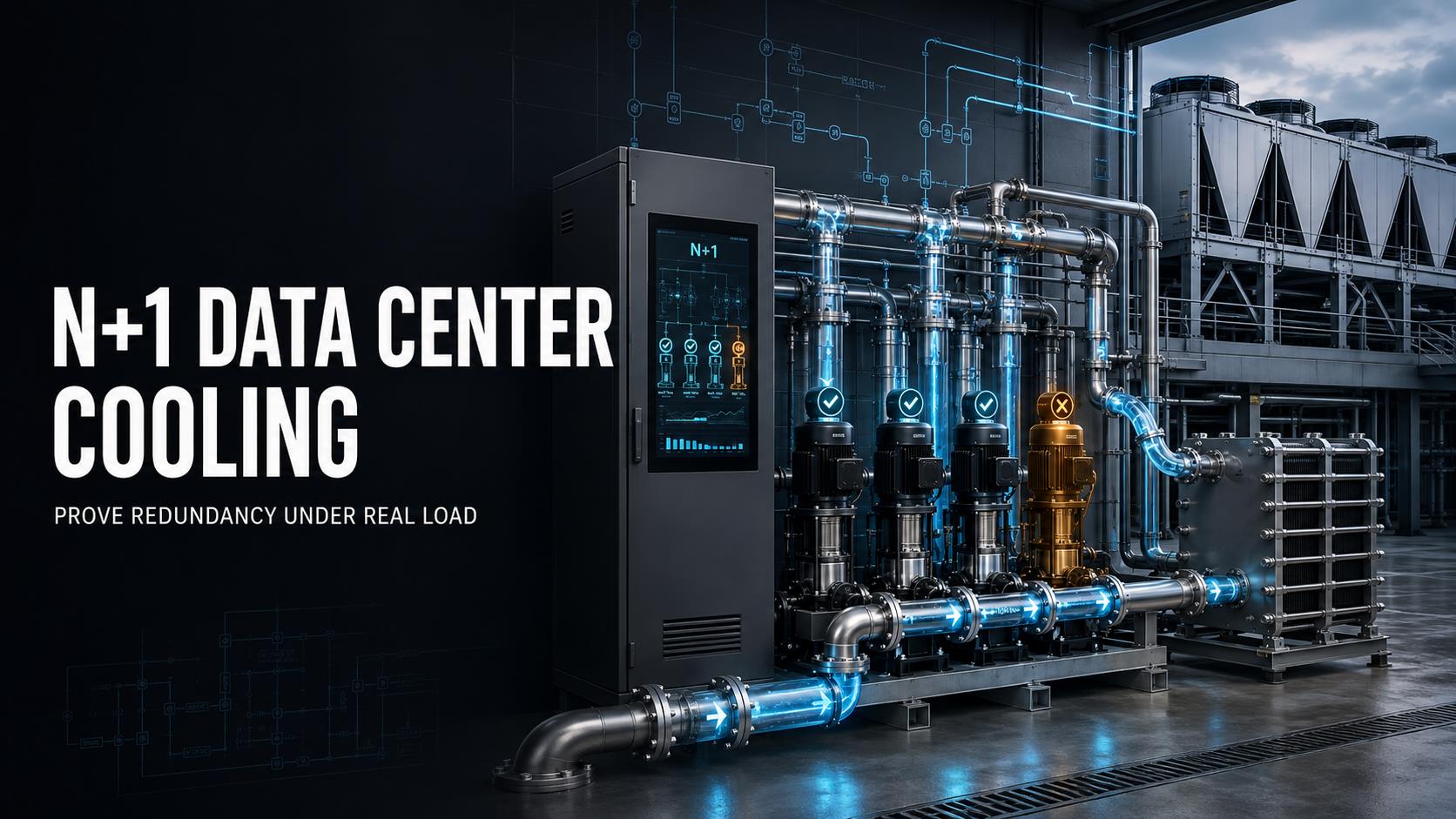
“N+1” appears in the design documents. Then one pump is isolated, a dry cooler module is taken offline, or a control circuit fails. The supply temperature starts climbing, remote racks lose flow, and the operator has to reduce IT load.
At that point, the system may have N+1 equipment on paper, but not N+1 performance in operation.
The real question is not how many pumps, CDUs, or dry coolers have been installed. The real question is whether the remaining equipment can maintain the required thermal and hydraulic conditions after one active component is unavailable.
That is why N+1 data center cooling must be proven under real or representative load.
What N+1 Actually Means in Data Center Cooling
In a cooling system, N is the minimum capacity required to support the defined full IT load under specified operating conditions.
The “+1” is one additional capacity component that can take over when one of the required components is unavailable.
For example, assume a cooling plant requires four identical units to support a 1.2 MW thermal load:
Four units are required for normal operation.
N equals four.
N+1 requires five units.
After one unit is unavailable, the remaining four units must still support the required 1.2 MW load.
The final condition is the important part. If the remaining units cannot deliver the required cooling capacity, flow, pressure, or temperature after the failure, the design does not provide functional N+1 redundancy.
This capacity-based definition is consistent with explanations from Vertiv and CoreSite. N+1 is based on the capacity needed to support the full load, plus one additional component for failure protection.
Capacity Is Not the Same as Nameplate Rating
A unit’s rated capacity is only meaningful under its stated test conditions.
Actual cooling capacity can change with:
Entering and leaving fluid temperatures
Design outdoor ambient temperature
Coolant type and glycol concentration
Flow rate and available pressure
Fan speed or pump speed
Coil fouling and filter loading
Heat exchanger approach temperature
Airflow recirculation
Control sequence and operating mode
A dry cooler may be rated to reject a certain amount of heat under a specific ambient temperature and fluid condition. That rating does not automatically mean the same output will be available during a high-ambient event or after one module is shut down.
The same logic applies to CDUs and pumps. A pump rated for a certain maximum flow may not deliver that flow at the actual system pressure head.
Pro Tip: Define N+1 using usable capacity at the project design condition, not the highest number printed on a product datasheet.
Redundancy Must Be Defined by Function
A complete cooling system contains several functional layers. Each layer can have a different redundancy level.
A project may have:
N+1 cooling pumps
N+1 CDU modules
N+1 dry cooler modules
Redundant power supplies
Redundant PLCs or controllers
Redundant temperature and pressure sensors
Dual communication paths
Multiple headers and branch circuits
These layers do not automatically create system-level redundancy.
For example, a system may include two pumps but still depend on:
One shared electrical panel
One common PLC
One isolation valve
One suction header
One discharge header
One temperature sensor
One control communication link
If any of these shared elements can stop the entire cooling loop, the system still has a single point of failure.
N+1 should therefore be written as a functional statement:
With one defined failure mode active, the cooling system must continue to support the required load within the agreed temperature, flow, pressure, and control limits.
That statement is much more useful than simply saying “the project includes N+1 pumps.”
How to Verify N+1 Cooling Pumps
Pump redundancy is often the first item discussed in liquid cooling projects. It is also one of the easiest areas to misunderstand.
A typical pump arrangement may include several pumps operating in parallel. One pump is designated as standby, or all pumps operate together at partial load. Both configurations may be valid, but they must be tested differently.
The remaining pumps must be evaluated at the actual system duty point, not only at the pump’s maximum rated flow.
The verification should consider:
Required total flow
Required differential pressure
Pump curve at the operating speed
Variable-frequency drive limits
Pipe and manifold pressure drop
Filter pressure drop
Coolant viscosity
Glycol concentration
Control valve position
Worst-case branch flow
Minimum flow requirements
Pump start and ramp-up behavior
A simple capacity check can be expressed as:
Required cooling capacity = mass flow x specific heat x supply-return temperature difference
If one pump is removed, the remaining pumps must still provide enough mass flow and pressure for the required heat load.
A pump that starts successfully but cannot maintain remote branch flow does not provide useful redundancy.
What to Record During a Pump Failure Test
Before isolating a pump, record the baseline condition:
Supply temperature
Return temperature
Total loop flow
Pump differential pressure
Pump speed
Filter differential pressure
Remote branch flow
CDU inlet and outlet temperatures
Rack or server-side inlet temperature
Active alarms
IT load and cooling load
Then isolate one active pump and record the system response.
The test should confirm:
The failed pump is detected.
The standby pump receives the correct start command.
The pump reaches the required operating speed.
Total flow returns to the required range.
Differential pressure remains sufficient at the remote branch.
No pump cavitation or unstable oscillation occurs.
Cooling temperature remains within the project limit.
The monitoring system reports the correct status.
Pro Tip: A pump failover test should include the most hydraulically remote branch. A CDU outlet may look stable while a far-end rack is already receiving insufficient flow.
Redundant CDU System: Pump Backup or Module Backup?
A redundant CDU system can be configured in several ways. These configurations should not be described as equivalent.
Dual Pumps Inside One CDU
A CDU with two pumps may provide redundancy for the pumping function.
However, the following components may still remain common:
Heat exchanger
Controller
Electrical supply
Temperature sensors
Pressure sensors
Expansion tank
Valves
Internal piping
Communication interface
If the heat exchanger or controller fails, the second pump cannot solve the problem.
N+1 CDU Modules
An N+1 CDU module arrangement provides a broader level of protection. One complete CDU module is taken offline, and the remaining modules must maintain the required performance.
The test should confirm:
Secondary-side supply temperature
Secondary-side return temperature
Primary-side flow
Secondary-side flow
Differential pressure
CDU heat transfer performance
Pump status
Valve position
Automatic control response
Alarm and BMS communication
The test condition must include the intended load. Running the test at 30% load may show that the backup module starts. It does not prove that the remaining system can support the required design load.
A proper CDU redundancy specification should identify whether the project requires:
Pump redundancy
Heat exchanger redundancy
Complete CDU module redundancy
Control redundancy
Electrical redundancy
Maintenance bypass capability
These are separate procurement decisions.
Dry Cooler Redundancy Is More Than Adding Extra Fans
Dry cooler redundancy is also easy to oversimplify.
There is a major difference between:
One fan failing
One fan bank failing
One coil section being isolated
One complete dry cooler module being unavailable
One electrical or control circuit failing
A dry cooler with multiple fans may continue operating after one fan fails. That can be a useful level of protection, but it does not automatically equal N+1 dry cooler module redundancy.
The test must define the failure unit.
If the failure scenario is one fan, the system should verify the remaining fan array. If the failure scenario is one complete dry cooler module, the remaining modules must reject the full required heat load at the specified design ambient condition.
The evaluation should include:
Design outdoor ambient temperature
Entering fluid temperature
Leaving fluid temperature
Target approach temperature
Total heat rejection load
Airflow direction
Hot-air recirculation risk
Fan speed control
Coil face coverage
Coil and fin cleanliness
Electrical feeder arrangement
Header arrangement
Freeze protection where applicable
Alarm and control logic
A system may pass a dry cooler redundancy test during mild weather but fail during the summer design condition. The test result is only meaningful when the ambient and fluid conditions are clearly defined.
Read more about the role of outdoor heat rejection in the Dry Cooler product architecture.
Pro Tip: Always distinguish “one fan offline” from “one dry cooler offline” in the RFQ, FAT, SAT, and commissioning documents. They are different failure scenarios with different capacity consequences.
Why Real-Load Testing Matters
A low-load test can confirm that a standby unit starts. It cannot confirm that the cooling system can maintain the required load after a failure.
High-density AI racks and other continuous workloads can leave very little thermal margin. A delayed failover may create a rapid temperature increase in the affected branch before the entire system shows an alarm.
A real-load or representative-load test should be performed under a controlled and approved procedure.
The load may come from:
Live IT equipment
A heat load bank
A controlled simulation of the expected IT load
A staged load profile that reproduces the planned operating condition
The test should never exceed equipment limits or create an uncontrolled risk to the IT system. At the same time, it should be large enough to represent the condition the redundancy design is supposed to protect.
A Practical Cooling Failover Test Sequence
Step 1: Establish the Baseline
Operate the system at the agreed test load until temperatures and flow conditions are stable.
Record:
IT load
Cooling load
Supply and return temperatures
Flow rate
Differential pressure
Pump and fan speed
CDU status
Dry cooler leaving temperature
Rack inlet conditions
BMS and DCIM status
Step 2: Remove One Active Component
Intentionally isolate one active pump, CDU module, or dry cooler module according to the approved test script.
The test should identify the exact time of failure initiation.
Step 3: Verify Detection and Control Response
Check whether the system:
Detects the failure
Generates the correct alarm
Starts the standby unit
Opens or closes the correct valves
Adjusts pump or fan speed
Maintains communication with the BMS
Avoids unnecessary shutdown commands
Step 4: Observe the Stabilization Period
The backup equipment may need time to start, ramp, and stabilize. Record the thermal and hydraulic response during this period.
Pay particular attention to:
Temperature overshoot
Flow oscillation
Pressure drop
Uneven branch distribution
Pump cavitation
Fan ramp behavior
Unstable valve movement
Local rack temperature increase
Step 5: Confirm the Acceptance Criteria
The system should be evaluated against project-specific criteria, including:
Required cooling load maintained
Supply temperature within limit
Return temperature within expected range
Minimum flow maintained at critical branches
Differential pressure maintained
No uncontrolled temperature oscillation
No IT derating
No emergency shutdown
Correct alarm transmission
Correct equipment status
Redundancy restored after the test
Step 6: Repeat the Test Where Required
One successful test is not always enough. If the project includes different operating modes, test each applicable mode.
Examples include:
Normal operation
Partial-load operation
Maximum design load
High-ambient operation
Maintenance mode
Automatic mode
Manual override mode
Communication loss mode
Commissioning guidance commonly separates factory checks, pre-installation verification, functional performance testing, and integrated system testing. This progression is useful because a component can pass its individual test while the complete cooling system still fails during an integrated failure scenario.
Recommended N+1 Failure Test Matrix
| Test Scenario | Failure Introduced | What Must Be Verified |
|---|---|---|
| Pump failure | One active pump isolated | Flow, pressure, automatic start, remote branch performance |
| CDU pump failure | One CDU pump unavailable | Pump failover, CDU control, secondary loop stability |
| CDU module failure | One complete CDU module offline | Remaining heat transfer capacity and temperature control |
| Dry cooler fan failure | One fan or fan bank offline | Remaining airflow, fan staging, heat rejection |
| Dry cooler module failure | One complete dry cooler unavailable | Heat rejection under design ambient conditions |
| Filter loading | Increased filter pressure drop | Pump head, flow stability, alarm response |
| Sensor failure | Temperature or pressure sensor unavailable | Sensor redundancy and safe control response |
| Communication loss | BMS or controller communication interrupted | Local control, alarm reporting, fail-safe behavior |
| Power path failure | One defined feeder or control power path offline | Equipment availability and automatic transfer logic |
The matrix should be agreed before commissioning. It should also identify the expected failure duration and recovery procedure.
Acceptance Criteria Must Be Written Before Procurement
Many redundancy disputes begin because the project team defines the equipment but not the pass or fail condition.
Before placing an order, specify:
The required thermal load
The design ambient condition
Supply and return temperature limits
Required flow rate
Minimum differential pressure
Fluid type and glycol concentration
Failure unit
Failover mode
Maximum response time
Stabilization period
Maximum allowable temperature excursion
IT derating requirements
Alarm and BMS requirements
Data logging requirements
Test witness requirements
Retest procedure after corrective action
Do not use a vague requirement such as:
“The system shall be N+1.”
Use a measurable statement instead:
“With one defined pump, CDU module, or dry cooler module unavailable, the remaining cooling system shall maintain the specified thermal load, supply temperature, flow, differential pressure, monitoring status, and IT operating condition for the agreed test duration.”
The exact limits must come from the project design, equipment manufacturer, IT hardware requirements, and owner’s operating criteria.
Common N+1 Mistakes
1. Counting Equipment Instead of Capacity
Five small units do not automatically provide N+1 for a load that requires the full output of four large units.
2. Testing at Low Load
A low-load test verifies startup behavior, not full-load resilience.
3. Measuring Only at the CDU Outlet
The closest measurement point may look normal while the most remote rack has insufficient flow or excessive temperature.
4. Ignoring Shared Infrastructure
A redundant pump cannot compensate for a single common panel, controller, header, valve, or sensor.
5. Ignoring High Ambient Conditions
Dry cooler output can be affected by outdoor temperature, approach temperature, airflow organization, and heat recirculation.
6. Treating a Dual-Pump CDU as a Fully Redundant CDU
Two pumps protect one function. They do not necessarily protect the heat exchanger, controls, power supply, valves, or instrumentation.
7. Confusing N+1 With 2N
N+1 adds one extra capacity component. 2N duplicates the complete required system, normally with independent paths. The cost, footprint, controls, and operational strategy are different.
8. Having No Defined Failure Duration
A system may survive a short interruption but fail after the standby equipment has to operate continuously. The test duration must be defined.
What Buyers Should Request From the Supplier
Before approving a cooling package, request evidence for:
Cooling capacity at design conditions
Pump curves and system duty points
Flow and pressure calculations
CDU heat exchanger performance
Dry cooler performance at design ambient temperature
Control sequence of operation
Failure detection and automatic failover logic
Single-line diagrams
Piping and instrumentation diagrams
Electrical distribution drawings
Sensor and alarm lists
FAT procedure
SAT procedure
Integrated cooling failover test procedure
Commissioning records
Data logging format
Warranty responsibilities
Corrective action and retest process
A supplier should be able to explain exactly what “N+1” covers in the proposed system.
Is it:
One pump?
One CDU?
One dry cooler fan?
One complete dry cooler module?
One electrical feeder?
One control path?
One complete cooling train?
The answer should appear in the technical proposal, not remain as an assumption.
Final Verdict: Prove N+1 Where the Load Actually Lives
N+1 data center cooling is not proven by the number of spare units installed.
It is proven when one defined active failure is introduced and the remaining system continues to maintain:
Required cooling capacity
Supply temperature
Return temperature
Flow
Pressure
Rack or server inlet conditions
Control stability
Alarm visibility
IT operating performance
For a liquid-cooled AI facility, that means testing the complete chain:
Heat load → CDU → pumps → manifolds → racks → return loop → dry cooler → controls
A project may have redundant pumps and still fail because of a blocked filter. It may have redundant CDUs and still fail because of one shared controller. It may have redundant dry coolers and still lose capacity because of high ambient temperature or hot-air recirculation.
The safest procurement approach is simple: define the failure, define the load, define the operating limits, and require recorded evidence.
To discuss a cooling architecture for a high-density AI or modular data center project, contact the ACT technical team.