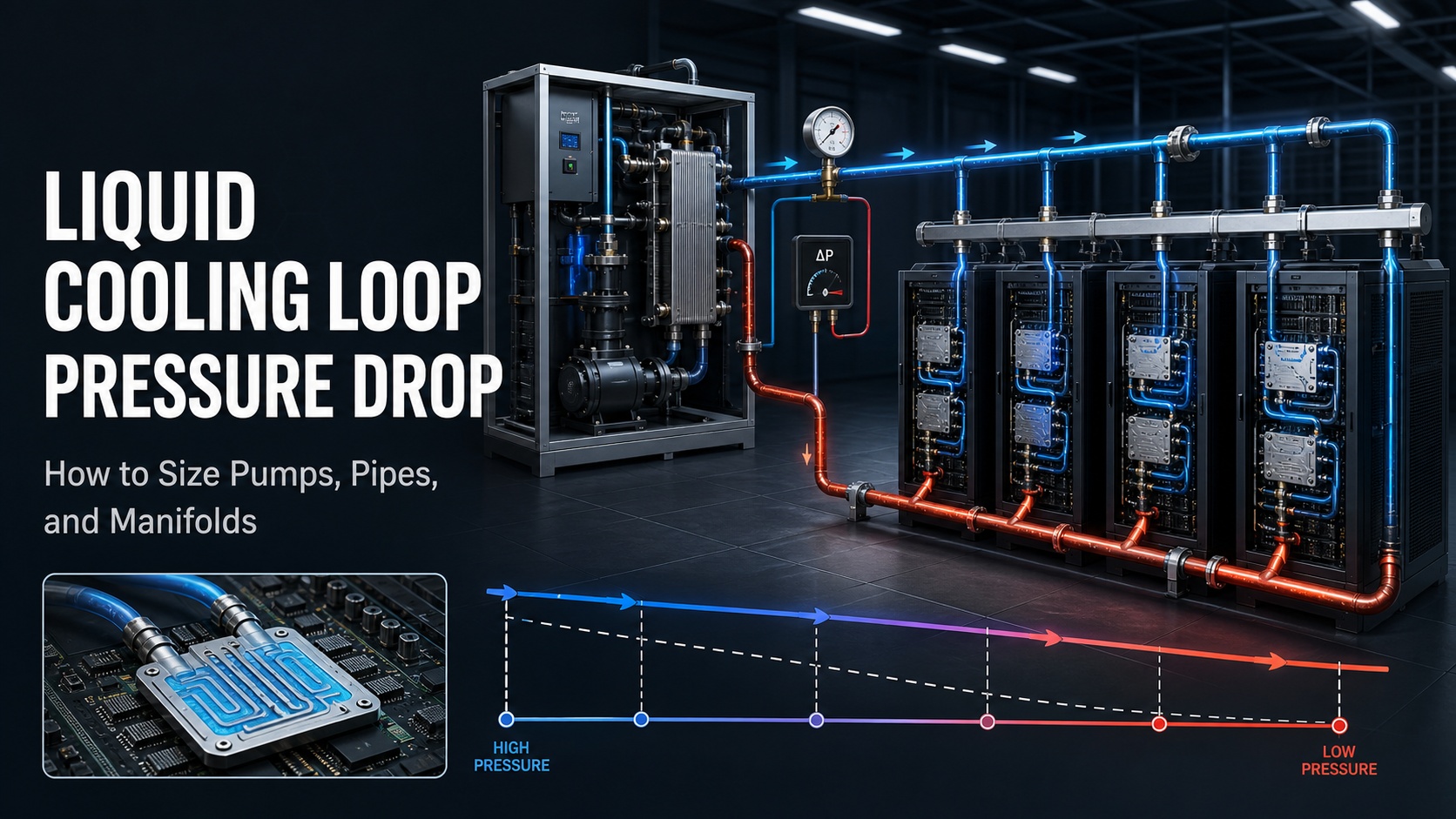
The pump is running. The CDU display shows a normal flow value. Yet the remote AI rack is still running hotter than expected.
This is one of the most common hydraulic problems in high-density liquid cooling systems. The pump may be operating correctly at the CDU outlet, while the farthest rack receives insufficient flow because the system has too much resistance.
That is the engineering problem behind liquid cooling loop pressure drop.
A liquid cooling system does not deliver its design flow simply because the pump is switched on. The pump must provide the required flow at the required pressure head after overcoming every restriction in the loop.
The correct design sequence is:
Heat load → coolant flow rate → component pressure drop → critical path → pump head → pipe size → manifold balance → commissioning
Why a Running Pump Does Not Guarantee Enough Flow
Flow and pressure are connected, but they are not the same thing.
Flow tells you how much coolant is moving.
Pressure head tells you whether the pump can move that coolant through system resistance.
Pressure drop describes the resistance created by pipes, fittings, cold plates, filters, valves, manifolds, and heat exchangers.
A pump may be running at full speed while the remote rack receives too little coolant. This can happen when:
The pump curve was selected only by maximum flow.
The pipe network has excessive friction loss.
Quick disconnects or hoses are undersized.
The manifold is not balanced.
A filter is partially blocked.
Air is trapped in the loop.
The coolant contains more glycol than assumed during design.
The CDU outlet is being measured instead of the worst-case branch.
The first lesson is simple:
A CDU flow reading is not the same as a remote rack flow reading.
Step 1: Convert Heat Load into Coolant Flow
Pump and pipe sizing should start with the actual heat load entering the liquid loop.
The basic heat-balance relationship is:
Q = m × Cp × Delta T
Where:
Q is the heat load.
m is the mass flow rate.
Cp is the specific heat of the fluid.
Delta T is the temperature difference between supply and return.
For water, a practical early-stage approximation is:
Flow rate in m³/h ≈ Heat load in kW ÷ (1.163 × Delta T in °C)
Example: 100kW AI rack cooling
| Design Delta T | Approximate Water Flow | Approximate Flow in L/min |
|---|---|---|
| 5°C | 17.2 m³/h | 287 L/min |
| 7°C | 12.3 m³/h | 205 L/min |
| 10°C | 8.6 m³/h | 143 L/min |
These values are suitable for preliminary calculation only. The final design must use the actual coolant properties at the operating temperature.
A water-glycol mixture changes:
Specific heat
Density
Viscosity
Pressure drop
Pump power
Heat-transfer performance
A project that calculates flow using pure water and later fills the system with glycol may not achieve the expected flow or cooling capacity.
Rack power is not always liquid cooling load
A 120kW rack does not automatically mean that the CDU must remove exactly 120kW.
The actual liquid-side load depends on the cooling architecture. Direct-to-chip cooling, rear-door heat exchangers, immersion cooling, and hybrid systems transfer different percentages of rack heat into the liquid loop.
For a rack with:
Total rack power: 120kW
Liquid heat capture: 90%
The initial liquid-side load is approximately:
120kW × 90% = 108kW
The final CDU selection still needs to account for pump heat, operating margin, future expansion, and redundancy.
Pro Tip: Ask the server or rack supplier for peak thermal load and liquid heat capture percentage. Average rack power is not enough for AI workloads that can change rapidly during training or inference.
Step 2: Build a Complete Pressure-Drop Budget
Once the coolant flow rate is known, the next task is to calculate the pressure drop through the complete hydraulic path.
A simplified pressure-drop budget is:
Total pressure drop = CDU loss + heat exchanger loss + cold plate loss + manifold loss + hose and quick disconnect loss + filter loss + valve loss + pipe loss
Every value should be checked at the required design flow and with the actual coolant.
Main sources of pressure drop
CDU and heat exchanger
The CDU may contain:
Pumps
Plate heat exchangers
Filters
Control valves
Flow meters
Internal manifolds
The supplier should provide pressure-drop data at different flow rates. A CDU with a high nominal capacity may still require a significant pump head because of internal resistance.
Cold plates and server manifolds
Cold plates can create a substantial pressure drop, especially at high flow rates. The pressure loss depends on:
Cold plate design
Channel geometry
Required flow per plate
Number of cold plates
Manifold arrangement
Coolant viscosity
The correct calculation must use the actual cold plate and server configuration.
Quick disconnects and hoses
Quick disconnects are often overlooked during early design. Several small restrictions in series can create a meaningful pressure loss.
Review:
Internal diameter
Connection size
Flow direction
Pressure rating
Manufacturer pressure-drop curve
Number of connections per branch
A hose with a large outside diameter may still have a small internal passage.
Filters and strainers
A clean filter and a loaded filter do not have the same pressure drop.
The design should include:
Clean-filter pressure drop
Expected loading condition
Service threshold
Differential-pressure sensor
Bypass strategy where appropriate
A filter can quietly become the reason a remote rack loses flow.
Valves and balancing devices
Control valves and balancing valves consume differential pressure. If the valves are oversized, they may provide poor control authority. If they are undersized, they may create unnecessary pressure loss.
The design should show the expected valve position at normal operation and the pressure drop at the design flow.
Closed-Loop Elevation: Do Not Double-Count Static Head
Elevation needs careful treatment.
In a sealed closed liquid loop, the static pressure created by raising the supply line is largely recovered when the return line descends. The pump normally does not need to overcome the entire building height in the same way that it would in an open system.
Do not automatically add every meter of vertical pipe to the pump head.
Elevation still matters for:
Minimum pressure at high points
Air removal
Fill pressure
Expansion tank location
Pump suction conditions
NPSH margin
Systems connected to an open tank
Systems with different fluid levels
For a closed loop, friction and component pressure drop usually define the pump duty point. For an open or partially open system, static head may need to be included directly.
This distinction can prevent both under-sizing and unnecessary pump oversizing.
Step 3: Use Darcy-Weisbach for Pipe Friction
Pipe friction depends on more than the pipe length.
A commonly used relationship is:
Delta P = f × (L/D) × (rho × v² / 2)
Where:
Delta P is pipe friction pressure drop.
f is the friction factor.
L is pipe length.
D is internal pipe diameter.
rho is fluid density.
v is fluid velocity.
The calculation should include:
Actual internal diameter
Straight pipe length
Elbows
Tees
Reducers
Flexible hoses
Valves
Filters
Quick disconnects
Fluid temperature
Fluid viscosity
Glycol concentration
Fittings can be represented through equivalent length or local loss coefficients.
Pipe diameter is an operating decision
A smaller pipe may reduce initial material cost, but it can cause:
Higher fluid velocity
Higher friction loss
Greater pump energy
More sensitivity to fouling
Higher noise
Less expansion capacity
A larger pipe reduces friction, but it can increase:
Material cost
Insulation cost
Valve and fitting size
Installation space
Fluid volume
Drain and refill time
The correct pipe size is the one that meets the required flow and pressure-drop target under the actual operating conditions.
Do not size the main pipe from total rack power alone. Size each section according to the flow it actually carries.
Step 4: Select the Pump at the Real Duty Point
The pump should be selected using a defined duty point:
Required flow at required pressure head
A pump rated at 15m³/h may deliver that flow only at a very low pressure. Once the system includes cold plates, filters, manifolds, valves, and long pipes, the actual operating point may be much lower.
The pump selection should consider:
Design flow rate
Total dynamic head
Fluid density
Fluid viscosity
Operating temperature
Pump efficiency
Minimum stable flow
Variable-speed operating range
NPSH available and required
Pump heat added to the loop
Standby or redundant pump strategy
Future fouling and expansion margin
Pressure can be converted into pump head using:
H = Delta P ÷ (rho × g)
For water, 100kPa is approximately equal to 10.2m of water head. The conversion changes with fluid density, so a water-glycol system should use the actual density.
Illustrative pressure budget
The following example is for explaining the calculation method only. It is not a product specification.
| System Section | Illustrative Pressure Loss |
| CDU and heat exchanger | 45kPa |
| Cold plates and rack manifolds | 70kPa |
| Hoses and quick disconnects | 30kPa |
| Filters and valves | 25kPa |
| Pipes and fittings | 30kPa |
| Total calculated loss | 200kPa |
For water, 200kPa is approximately 20.4m of head before any project-approved operating margin is added.
The pump must be able to deliver the required flow at this pressure head. The maximum flow number printed on a pump datasheet is not enough.
Pro Tip: Put this requirement directly into the RFQ: “The CDU shall provide the specified flow rate at the specified differential pressure using the specified coolant.” This is much more useful than asking for maximum pump flow.
Step 5: Understand the Pump Curve and System Curve
A pump curve describes the pressure head a pump can provide at different flow rates.
A system curve describes how much pressure the cooling loop requires at different flow rates.
The operating point is where the two curves intersect.
If the system resistance is higher than expected:
The operating flow decreases.
Pump speed may rise.
Control valves may remain fully open.
Remote branches may become under-supplied.
Rack temperature may increase.
Low-flow alarms may appear only after the system reaches a higher load.
A variable-speed pump can adjust its output, but it cannot remove a blocked filter, trapped air pocket, undersized hose, or badly balanced manifold.
The design should identify:
Normal operating point
Peak design point
Minimum flow condition
Redundant operating point
Pump failure condition
Expected filter-loaded condition
Future expansion condition
Pump selection should also avoid operating continuously at the extreme end of the curve. A stable operating range gives the controls more room to respond to workload changes and system resistance.
Step 6: Control Manifold Pressure Drop and Branch Imbalance
Parallel rack branches do not automatically receive equal flow.
Coolant prefers the branch with lower resistance. A nearby rack with short piping may receive more flow, while a remote rack with longer piping, more fittings, or a smaller hose receives less.
This is the main reason manifold pressure drop must be reviewed at the branch level.
A good manifold design should consider:
Number of rack branches
Flow per branch
Branch pipe diameter
Branch length
Cold plate pressure drop
Quick disconnect pressure drop
Balancing valve position
Header pressure loss
Available differential pressure
Flow measurement method
Future branch connections
Possible balancing methods include:
Balancing valves
Fixed orifices
Flow-control valves
Reverse-return piping
Branch flow meters
Differential-pressure sensors
Automatic control valves
The correct method depends on the system layout and control strategy.
For critical AI racks, the supplier should identify the worst-case branch and confirm that it receives the required flow while other branches remain within their operating range.
Do not evaluate a manifold only by the number of connection ports. A manifold with many ports may still perform poorly if its header is undersized or its branches are not balanced.
Step 7: Treat Filters, Air, and Glycol as Hydraulic Design Inputs
Filter loading
A filter should be selected for both clean and loaded conditions.
The monitoring system should track filter differential pressure. The alarm threshold should be defined before deployment, not invented after the rack starts overheating.
A practical maintenance plan should specify:
Normal differential pressure
Warning level
Shutdown or protection level
Replacement procedure
Spare filter availability
Safe isolation method
Air in the loop
Air pockets can cause:
Flow fluctuations
Pump noise
Cavitation risk
Unstable temperature readings
Reduced heat transfer
Intermittent low-flow alarms
High points should be reviewed during piping design. The commissioning process should include proper filling, venting, pressure testing, and deaeration.
A pump can show unstable behavior even when there is no visible leak. Trapped air is one of the first conditions to investigate.
Glycol concentration
Glycol is often needed for freeze protection or specific site conditions, but it changes the hydraulic design.
At higher concentration, glycol can increase viscosity and pressure drop while reducing specific heat. The pump, pipes, and heat exchanger must be selected using the actual mixture and operating temperature.
The RFQ should state:
Fluid type
Glycol concentration
Minimum operating temperature
Maximum operating temperature
Required water quality
Corrosion inhibitor requirements
Filtration requirements
Step 8: Verify Flow at the Remote Rack
Factory testing at the CDU outlet is useful, but it does not prove that the complete rack loop will operate correctly.
The most important field measurement is usually taken at the remote or highest-resistance branch.
Commissioning should include:
Confirm the actual fluid and concentration.
Verify TCS supply and return temperatures.
Record CDU outlet flow.
Record flow at the farthest branch.
Measure supply and return pressure.
Measure branch differential pressure.
Check filter differential pressure.
Confirm valve positions.
Test pump speed response.
Run a load-step test.
Test operation with one redundant pump unavailable.
Verify BMS or DCIM alarms.
The test should be performed at the specified thermal condition. A loop that passes at low load may still fail when the AI workload reaches its peak.
The acceptance report should record:
Flow rate
Pressure head
Supply temperature
Return temperature
Delta T
Pump speed
Filter differential pressure
Branch balance
Alarm status
Failure-mode performance
This turns “the pump is running” into a measurable operating result.
What Buyers Should Include in a CDU RFQ
A supplier cannot complete a reliable CDU pump head calculation from the phrase “CDU for a 100kW rack.”
The RFQ should include:
Number of racks
Peak rack heat load
Average rack heat load
Percentage of heat captured by liquid
Server and GPU model
Required coolant flow rate
TCS supply temperature
TCS return temperature
FWS supply temperature
FWS return temperature
Coolant type
Glycol concentration
Maximum allowable pressure drop
Cold plate pressure drop
Manifold arrangement
Pipe sizes and lengths
Hose and quick disconnect information
Filter type and loading limit
Site elevation
High-point and low-point locations
Redundancy requirement
BMS or DCIM communication protocol
Required alarms
Future expansion plan
Required factory and site acceptance tests
Ask the supplier to provide:
Pump curve
System curve or design resistance
Guaranteed flow at pressure head
Component pressure-drop table
Normal operating capacity
Redundant operating capacity
Minimum operating flow
Filter-loaded performance
Control sequence
Alarm list
FAT and SAT procedure
Common Hydraulic Design Mistakes
Mistake 1: Selecting the pump by maximum flow
Maximum flow is normally measured under low resistance. It does not represent the actual project duty point.
Mistake 2: Testing only at the CDU outlet
The outlet may show normal flow while the remote rack is under-supplied.
Mistake 3: Using pure-water data for glycol
The calculation can underestimate pressure drop and pump power.
Mistake 4: Treating all rack branches as identical
Small differences in pipe length, fittings, hoses, and cold plate resistance can create meaningful flow imbalance.
Mistake 5: Adding the full building height to a closed-loop pump calculation
This can significantly oversize the pump if the loop is sealed and the return column balances the supply column.
Mistake 6: Oversizing the pump instead of fixing the restriction
A larger pump may increase noise, energy use, valve stress, and leak risk. It does not solve trapped air or a blocked filter.
Mistake 7: Forgetting the failure mode
The pump may provide enough flow in normal operation but fail to maintain the required flow after one pump or CDU module is unavailable.
Final Verdict
Reliable liquid cooling is a hydraulic design problem, not just a pump selection problem.
The correct sequence is:
Heat load → coolant flow rate → component pressure drop → critical path → pump duty point → pipe sizing → manifold balancing → monitoring → commissioning
For high-density AI racks, the key performance question is not:
“Is the pump running?”
It is:
“Does the remote rack receive the required flow at the required temperature and pressure under the real operating condition?”
A reliable liquid cooling system should provide:
Stable flow
Adequate pressure head
Balanced rack branches
Measurable filter loading
Effective air removal
Correct glycol calculation
Clear low-flow alarms
Tested pump redundancy
Verified remote-rack performance
For project-specific evaluation, review the ACT-Boxes CDU solution and Modular AI Data Center solution. You can also contact the engineering team with your rack heat load, coolant type, flow requirement, pipe layout, manifold design, and site conditions.
FAQ
What is liquid cooling loop pressure drop?
Liquid cooling loop pressure drop is the pressure difference required to move coolant through the pipes, cold plates, manifolds, filters, valves, hoses, quick disconnects, heat exchangers, and other system components.
How do I calculate CDU pump head?
First determine the design flow rate. Then add the pressure drop of the CDU, heat exchanger, cold plates, manifolds, filters, valves, pipes, fittings, and other critical-path components. Convert the final pressure requirement into pump head using the actual fluid density.
Why can a remote rack have low flow when the pump is running?
The pump may not be able to provide enough pressure at the required flow. Common causes include excessive pipe friction, undersized hoses, clogged filters, trapped air, incorrect valve positions, unbalanced manifolds, or glycol viscosity higher than expected.
Should elevation always be included in a closed-loop pump calculation?
Not as a simple full-height addition. In a sealed closed loop, the supply and return columns largely balance each other. Elevation still affects fill pressure, high-point air removal, NPSH margin, and systems connected to open tanks.
What should be tested before accepting a liquid cooling loop?
Test flow and pressure at the remote branch, not only at the CDU outlet. The project should also verify temperature control, filter differential pressure, valve position, pump failover, low-flow alarms, leak detection, BMS/DCIM communication, and performance under peak load.
RESEARCH REFERENCES
Schneider Electric, Liquid Cooling Solutions for Data Centers
https://www.se.com/ww/en/work/solutions/data-centers-and-networks/liquid-cooling/Vertiv, High-Density Cooling Solutions
https://www.vertiv.com/en-us/products-catalog/thermal-management/high-density-cooling/CoolIT Systems, Data Center Liquid Cooling
https://www.coolitsystems.com/Hydraulic Institute, Pump System Resources
https://www.pumps.org/ACT-Boxes CDU Product Page
https://blockchain-miner.com/product/cdu/ACT-Boxes Modular AI Data Center Page
https://blockchain-miner.com/product/ai-data-center/