A dry cooler can be selected for a 1MW heat load and still fail to maintain the design water temperature on a 1MW site.
The missing number is often not fan capacity. It is the temperature of the air actually entering the coil.
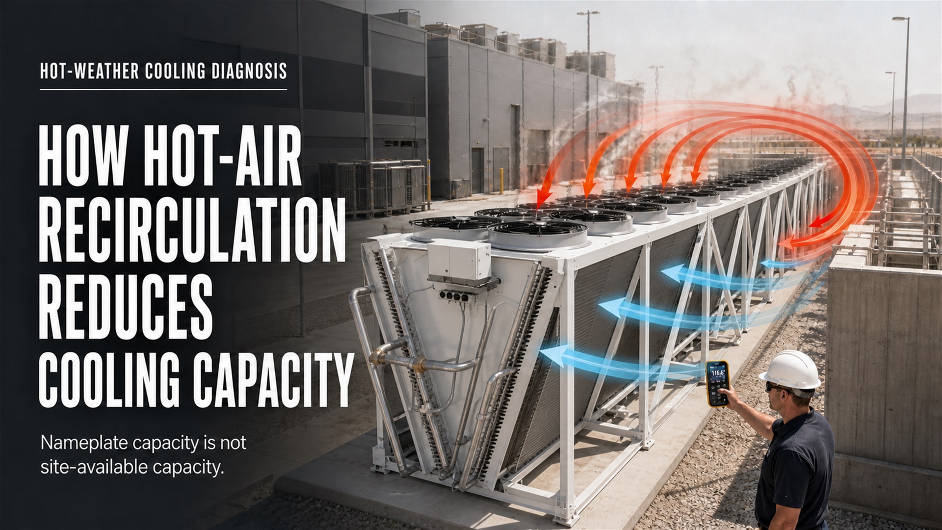
A weather station may report 104°F, while part of the dry-cooler coil is pulling in 111°F air because hot discharge has curled around a wall, crossed from an adjacent unit or returned beneath the fan bank.
The equipment is no longer operating at the condition used for selection.
As the entering-air temperature rises, the temperature difference available for heat rejection becomes smaller. Fan speed increases, leaving-fluid temperature rises, CDU operating margin disappears and the IT equipment may eventually have to reduce power.
This is how hot-air recirculation reduces cooling capacity without creating an obvious mechanical failure.
The fans are running. The pumps are running. The nameplate appears large enough.
The site still overheats.
Nameplate Cooling Capacity Is Conditional
Dry-cooler capacity is not a fixed number that remains available under every operating condition.
A manufacturer’s selection normally depends on several inputs:
Heat load
Entering-fluid temperature
Leaving-fluid temperature
Fluid flow rate
Water or glycol concentration
Design dry-bulb temperature
Site elevation
Coil condition
Fan operating point
Available electrical power
Change one of these values and the usable capacity changes.
Hot-air recirculation changes one of the most important values: entering-air temperature.
A practical site relationship is:
Actual coil entering-air temperature = Site ambient temperature + Recirculation gain + Local heat gain
Local heat gain may come from direct solar exposure, nearby transformers, generators, condensers, building exhaust or hot surfaces.
Therefore, the temperature displayed on a weather application is not necessarily the temperature experienced by the heat exchanger.
Pro Tip: Put the design ambient temperature and the maximum permitted coil entering-air temperature on separate lines in the technical agreement. They are not always the same number.
How Recirculation Destroys the Dry-Cooler Approach Temperature
The operating difficulty becomes clear when the approach temperature is calculated.
A simplified dry-cooler approach is:
Approach temperature = Leaving-fluid temperature − Actual coil entering-air temperature
Assume a system is selected to deliver 40°C leaving fluid at a 35°C entering-air temperature.
The design approach is:
40°C − 35°C = 5K
Now assume hot-air recirculation raises the coil entering-air temperature to 39°C.
The remaining approach is:
40°C − 39°C = 1K
Maintaining the same heat load and the same leaving-fluid temperature at a 1K approach may require substantially more coil surface, airflow or another heat-rejection method. In many installations, the existing dry cooler cannot maintain that condition.
The system finds a new operating balance instead:
The leaving-fluid temperature rises
Fans remain at maximum speed
Pumping may increase
CDU secondary-loop temperature rises
Server or miner inlet conditions move closer to their limit
IT power is reduced to keep temperatures under control
This is why a few degrees of recirculation gain can cause a large operating problem when the original design already uses a close approach.
More fan speed cannot restore a temperature difference that no longer exists.
Why Hot Exhaust Returns to the Coil
Hot-air recirculation is usually a site-level airflow problem rather than a single-component defect.
Common causes include:
Dry Coolers Installed Too Close Together
One unit can pull air discharged by the unit beside it. The risk increases when several dry coolers operate at full fan speed simultaneously.
Walls, Parapets and Noise Barriers
A wall may satisfy an acoustic or property-line requirement while trapping hot air around the equipment. The discharge plume rises, meets the obstruction and returns toward the coil intake.
Unequal Equipment Elevations
When adjacent coolers or fan cells are installed at different heights, discharge from one section may find a direct path into a lower intake.
Insufficient Bottom or Side Airflow Clearance
Dry coolers need access to a sufficient mass of outdoor air. Restricted clearance can increase inlet velocity, create uneven airflow and encourage hot discharge to return through the easiest available path.
EVAPCO’s dry-cooling guidance identifies airflow and heat-transfer surface area as key performance variables and notes that equipment elevation can be used to improve bottom airflow clearance.
Prevailing Wind and Crosswind
Wind can help remove the discharge plume, but the wrong wind direction can push it back toward the equipment. Performance may therefore change even when ambient temperature and IT load remain similar.
Adjacent Heat-Rejection Equipment
Dry coolers, chillers, generator radiators, transformers and building exhaust systems may interact. Each unit may be correctly selected when evaluated alone, while the combined site creates a much higher local air temperature.
HTRI documented this problem in an industrial air-cooled heat-exchanger case study. Its analysis found that equipment arrangement, ground clearance, lateral gaps and wind conditions created paths for hot-air recirculation. In that specific case, surrounding equipment and layout had the potential to affect performance substantially.
The lesson applies directly to modular data center campuses:
Do not evaluate the dry cooler as an isolated product. Evaluate the complete outdoor airflow field.
Six Customer Complaints and What They Usually Mean
| Customer Complaint | Possible Hidden Cause | What to Verify |
|---|---|---|
| The dry cooler nameplate is large enough, but water temperature keeps rising | Actual coil inlet temperature is above the design value | Multi-point coil inlet temperature versus true ambient |
| Performance drops when outdoor temperature approaches the design limit | The original selection has insufficient approach margin | Leaving-fluid target, ambient design point and selection curve |
| The weather station shows acceptable temperature, but the system overheats | Hot discharge is returning to part of the coil | Coil-face temperature map and wind direction |
| Fans are at full speed, but capacity does not recover | Temperature difference or airflow is insufficient | Fan operating point, coil resistance and recirculation gain |
| The system worked when new but now struggles in summer | Fins are dirty or airflow paths are blocked | Coil differential pressure, visual inspection and cleaning history |
| Capacity margin exists on paper, but the site still derates | Margin did not include dirty coils, fan failure or site recirculation | Combined worst-case operating model |
These symptoms often overlap.
For example, a dirty coil increases air resistance. The fans then move less air, discharge conditions change and the hot plume may become easier for neighboring equipment to recapture.
A failed fan can create a similar effect. The problem is not limited to losing the airflow of one fan. The failed fan cell may change pressure distribution across the entire bank.
Measure Recirculation Before Buying More Cooling Capacity
When water temperature rises, the fastest commercial response is often to add another dry cooler.
That may be the wrong investment.
If the existing equipment is pulling in its own discharge air, another unit installed in the same airflow pattern can make the recirculation problem worse.
Start with measurement.
At minimum, record:
True outdoor ambient temperature away from equipment discharge
Coil entering-air temperature at several positions
Dry-cooler discharge-air temperature
Fluid entering and leaving temperatures
Fluid flow rate
Fan speed, current and operating status
Differential pressure across the coil where available
Wind speed and direction
Operating status of adjacent equipment
IT load during the test
The basic recirculation gain is:
Recirculation gain = Average coil entering-air temperature − True outdoor ambient temperature
One average sensor is not enough.
Measure the upper, lower, center and end sections of the coil. In a multi-unit bank, measure the sides facing adjacent equipment as well.
If one section reads 4K or 5K higher than the upwind ambient sensor, the average value may hide a serious local capacity loss.
ASHRAE’s current AI data center energy framework emphasizes minimizing bypass and recirculation while using granular inlet monitoring rather than relying only on room-level measurements. The same monitoring logic should be applied to outdoor heat-rejection equipment.
Pro Tip: Trend coil entering-air temperature against wind direction. If cooling performance changes when the wind changes, the problem may be site airflow rather than insufficient nameplate capacity.
Correct the Airflow Path Before Increasing the Nameplate
The most cost-effective correction depends on the source of the recirculation.
1. Reorient the Equipment
Avoid placing the intake of one dry cooler directly in the discharge path of another. Review prevailing wind direction, seasonal wind variation and the simultaneous operation of all equipment.
2. Increase Effective Airflow Clearance
More clearance can give the fans access to cooler outdoor air and reduce inlet starvation. However, there is no universal spacing value for every dry cooler.
Use the manufacturer’s installation requirements and evaluate the actual site geometry.
3. Align Fan and Discharge Elevations
Mixed elevations can create short airflow paths between adjacent units. HTRI’s case study identified consistent fan elevation as one method for reducing recirculation in a multi-bay installation.
4. Seal Uncontrolled Gaps
Short gaps between units can become recirculation channels. Properly designed solid seals may close these paths.
Do not install random panels around the dry cooler. A poorly placed barrier can increase pressure loss or block fresh air.
5. Use Engineered Wind Walls or Screens
Wind walls and screens can redirect crosswind and limit plume return. They must be designed around fan airflow and structural wind loads.
A screen that reduces recirculation but starves the fan simply replaces one problem with another.
6. Raise or Redirect the Discharge
Higher discharge velocity or an elevated discharge path can help hot air move away from the intake zone. The final design must still account for noise, maintenance access and structural requirements.
7. Use CFD for Dense or High-Risk Layouts
Computational fluid dynamics becomes valuable when:
Several dry coolers are installed in rows
Walls or parapets surround the equipment
Equipment has different elevations
Prevailing wind approaches from several directions
The project uses a close dry-cooler approach
One fan or one unit must be allowed to fail
Extreme-weather output is commercially critical
CFD should not be used to decorate a proposal. It should answer specific questions about coil inlet temperature, plume direction and failure-mode performance.
Dust and Fan Failure Multiply the Recirculation Risk
Hot-air recirculation rarely appears alone.
Dust deposited on fins creates two penalties:
It reduces air passage and increases resistance.
It adds thermal resistance between the air and the coil surface.
As the coil becomes loaded, the fan operating point moves. Actual airflow may fall even when the fan is still running at the commanded speed.
Meanwhile, partial fan failure changes airflow distribution across the coil bank. A neighboring fan may pull air through an unintended path, including backward through an inactive fan section.
This is why separate calculations can be misleading.
A design may pass the hot-weather calculation with clean coils. It may also pass a one-fan-failure calculation at moderate ambient temperature. Yet it may fail when both conditions occur together.
The correct test condition is:
Design-day ambient + realistic coil loading + defined fan failure + expected recirculation allowance
Capacity margin and redundancy must also be separated.
Ten percent additional nameplate capacity does not automatically provide N+1 resilience. The remaining fans and coils must still maintain acceptable temperature, pressure and flow after the defined failure.
Pro Tip: Ask the supplier to state whether its quoted capacity applies to clean coils, fully operating fans and unrestricted ambient air. Then request the site-available capacity under the project’s maintenance and failure assumptions.
Plan the Extreme-Weather Derating Sequence
A well-engineered cooling system may still need controlled derating during rare weather events.
That is not automatically a design failure.
The failure is allowing the system to reach uncontrolled thermal alarms before the operating team knows how to respond.
A practical sequence can include:
Increase fan speed as leaving-fluid temperature rises.
Verify that actual coil inlet temperature remains within the design condition.
Alarm when recirculation gain exceeds the approved value.
Start standby fans, pumps or heat-rejection modules.
Activate approved adiabatic or mechanical backup cooling.
Raise the coolant setpoint only within validated server and CDU limits.
Reduce non-critical IT load in controlled stages.
Keep cooling equipment operating after load reduction to remove stored heat.
Restart IT equipment in stages after conditions recover.
Controls should use actual operating data, not only an outdoor weather sensor.
Important inputs include:
Coil entering-air temperature
Leaving-fluid temperature
Supply and return coolant temperature
Flow and pressure
Fan status
Pump status
Wind conditions
IT load
Alarm history
If the control system cannot distinguish high ambient temperature from hot-air recirculation, operators may repeatedly reduce IT load without correcting the physical airflow problem.
What Buyers Should Include in the Dry-Cooler RFQ
A request for quotation that only states “1MW dry cooler” is incomplete.
The buyer should provide:
Normal and maximum heat load
Project location
Site elevation
Summer design dry-bulb temperature
Wet-bulb temperature if adiabatic assistance is considered
Required entering and leaving fluid temperatures
Water or glycol concentration
Design fluid flow
Maximum allowable pressure drop
Equipment layout drawing
Nearby walls, buildings and heat sources
Prevailing wind data
Noise restrictions
Redundancy requirement
Maximum permitted recirculation gain
Dirty-coil operating assumption
Fan-failure operating requirement
Planned extreme-weather derating limit
The supplier should return:
Guaranteed capacity at the stated operating point
Fan operating point and power
Coil pressure-drop information
Minimum installation clearances
Allowable recirculation assumption
Performance with one fan or one unit unavailable
Sensor and alarm list
Control sequence
Cleaning and maintenance access
Site-layout recommendations
CFD scope where required
FAT and SAT acceptance criteria
Do not compare quotations until the suppliers are using the same entering-air temperature, fluid conditions and failure assumptions.
Calculate ROI From Site-Available Cooling Capacity
A lower-priced dry cooler does not create savings if recirculation forces repeated IT derating.
The financial exposure can be estimated as:
Cooling shortfall exposure = Curtailed IT MW × Contribution per MW-hour × Derating hours
Additional fan energy can be estimated as:
Added fan energy = Additional fan power × High-speed operating hours
The complete comparison should include:
Dry-cooler purchase cost
Structural and installation cost
Electrical distribution
Fan energy
Coil cleaning
Filter or screen maintenance
CFD and site engineering
Planned derating
Unplanned downtime
IT performance loss
Future expansion restrictions
A design with more airflow clearance or a better discharge arrangement may use more land. However, it can still produce a lower lifetime cost than a compact installation that continually recycles hot air.
Final Procurement Verdict
Buy site-available cooling capacity, not catalog capacity.
A dry cooler should not be approved because its nameplate matches the IT heat load. It should be approved when the supplier demonstrates that the required leaving-fluid temperature can be maintained using the actual coil entering-air temperature.
That evaluation must include site layout, wind, surrounding equipment, coil condition, fan failure and extreme-weather controls.
When the cooling margin is close, do not hide the risk inside a general safety factor.
Identify the recirculation allowance. Measure it during commissioning. Connect it to alarms and the derating sequence.
ACT-Boxes supports modular AI data center cooling infrastructure, including CDUs, dry coolers, liquid loops, controls, factory testing, delivery and commissioning coordination.
A useful configuration review begins with the IT heat load, coolant temperatures, fluid flow, glycol concentration, project climate, outdoor equipment layout, redundancy target and deployment schedule.
FAQ
Can a dry cooler deliver its nameplate capacity when hot air is recirculating?
Not necessarily. Nameplate or selected capacity is tied to a defined entering-air temperature and operating point. Recirculation raises the actual entering-air temperature and reduces the available temperature difference.
How much recirculation temperature gain is acceptable?
There is no universal value. The acceptable gain depends on the dry-cooler approach temperature and system operating limits. A 3K increase may be manageable in a system with substantial margin but critical in a close-approach design.
Will increasing fan speed solve hot-air recirculation?
It may temporarily increase airflow, but it cannot restore the lost temperature difference. In some layouts, higher discharge velocity or pressure interaction may also change the recirculation pattern.
How can operators detect recirculation?
Compare a true ambient sensor with multiple sensors across the coil intake. Record wind, discharge temperature, fluid temperatures, flow, fan status and adjacent-equipment operation at the same time.
When should a project use CFD?
CFD is valuable for dense equipment banks, restricted sites, walls or parapets, mixed equipment elevations, variable wind conditions and projects where extreme-weather capacity is commercially critical.
Should dry-cooler redundancy include dirty coils and hot weather?
Yes. Maintenance condition, design-day temperature, fan failure and recirculation should be evaluated together rather than as separate idealized cases.