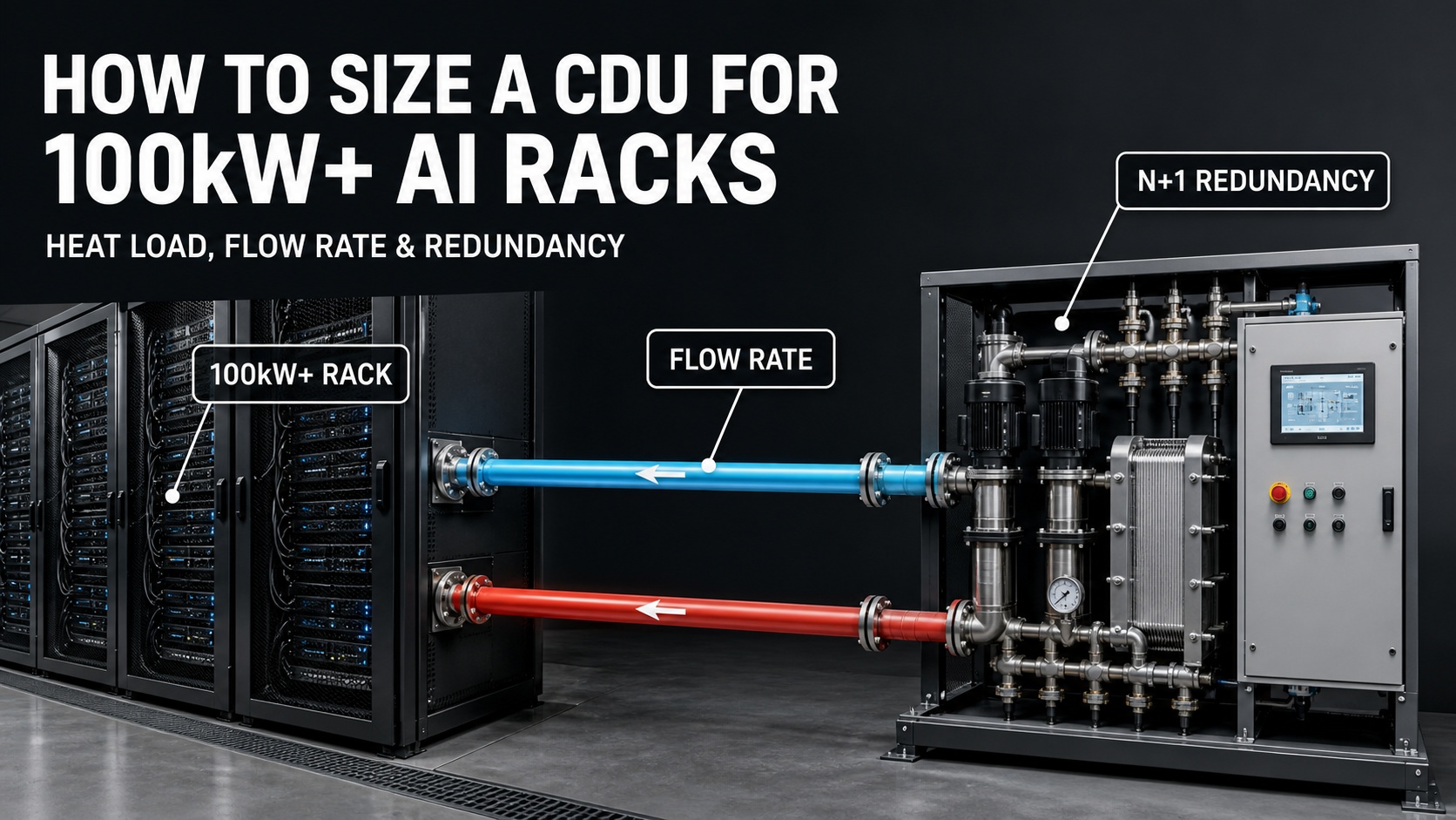
A data center can have hundreds of megawatts of planned power and still select the wrong CDU.
The problem usually starts when buyers use the total campus capacity as the primary cooling input. A 100MW or 360MW campus number does not tell you how much heat one rack produces, how much of that heat enters the liquid loop, what flow rate the cold plates require, or whether the system can continue operating after a pump or CDU module fails.
That is the real challenge behind CDU sizing for AI data center projects.
For 100kW+ AI racks, the CDU must be selected from the rack or pod level upward. The correct sequence is:
Define the liquid heat load. Set the temperature window. Calculate flow and pressure head. Then verify capacity and redundancy.
Why Total Campus MW Is the Wrong Starting Point
Total facility power is useful for utility planning, but it is too broad for CDU selection.
A campus power figure may include:
IT load
Cooling plant power
Pumps and fans
UPS losses
Power distribution losses
Lighting and auxiliary systems
Future expansion capacity
Reserved but not yet commissioned load
A CDU does not cool the entire electrical service. It removes heat from the cooling loop connected to a specific rack, row, pod, or containerized module.
For example, a 120kW AI rack may transfer most of its processor heat into a liquid loop, while memory, storage, power supplies, networking equipment, and other components may still reject part of their heat through air.
At steady state, nearly all electrical energy eventually becomes heat. The important question is where that heat is captured and which cooling system is responsible for removing it.
A CDU connected to one liquid loop should therefore be sized around:
Peak rack or pod heat load
Percentage of heat captured by liquid
Heat from pumps and loop components where applicable
Required operating margin
Future equipment changes
Redundancy requirements
Pro Tip: Ask your server or rack supplier for peak thermal load, not only average power consumption. AI workloads can create rapid load changes, and a CDU sized for the average may become unstable during training or inference peaks.
Step 1: Define the Heat Load the CDU Must Remove
The first number in a CDU selection is not the facility’s total megawatt capacity. It is the heat load entering the connected technology cooling system.
Peak load versus average load
A rack may operate at an average of 80kW but reach 110kW or 120kW during a high-intensity workload. If the CDU is selected using the average number, the loop may appear stable during light operation and then approach its limit when the GPUs ramp up.
For a proper high density rack cooling design, confirm:
Rated rack power
Maximum rack power
GPU and CPU thermal design power
Number of servers per rack
Expected workload profile
Percentage of heat captured by liquid
Heat from the rack-level pumps or controls
Number of racks served by one CDU
If a 120kW rack transfers 90% of its heat to the liquid loop, the liquid-side design load begins around 108kW before project-specific allowances are added.
That does not mean the CDU should automatically be selected as a 108kW unit. The final selection must also consider operating temperature, flow, pressure head, redundancy, and future expansion.
Rack load is not always CDU load
A CDU serving a direct-to-chip system may handle the heat from cold plates and related liquid-cooled components. A rear-door heat exchanger, immersion system, or hybrid architecture may send a different percentage of the total rack heat into the liquid loop.
This is why a GPU liquid cooling CDU should be selected together with the actual cooling architecture. The same rack power can create different CDU requirements under different heat-capture methods.
Step 2: Set the Supply, Return, and Facility Water Temperatures
Heat load alone cannot determine CDU size.
The second requirement is the temperature window.
A typical CDU separates two circuits:
The technology cooling system, or TCS, connected to the servers.
The facility water system, or FWS, connected to the building or outdoor heat-rejection plant.
The CDU transfers heat between these circuits while controlling the temperature and flow delivered to the IT equipment.
Before selecting the CDU, define:
TCS supply temperature
TCS return temperature
FWS supply temperature
FWS return temperature
Required temperature difference across the rack
CDU heat-exchanger approach temperature
Minimum and maximum operating temperatures
Site dew point and condensation margin
The role of Delta T
For the technology cooling loop:
Delta T = TCS return temperature – TCS supply temperature
A larger Delta T can reduce the flow required for the same heat load. That may reduce pump energy and make distribution easier.
A smaller Delta T requires more flow. This can increase pipe size, pump power, valve losses, and pressure-drop sensitivity.
The trade-off is not simply “higher Delta T is always better.” Server cold plates, manifolds, hose assemblies, heat exchangers, and control valves all have their own operating limits.
Approach temperature at the CDU
The CDU heat exchanger also has an approach temperature difference.
For a liquid-to-liquid CDU, the relevant temperature difference is typically related to the technology-loop supply temperature and facility-water inlet temperature. A smaller approach can improve temperature control, but it requires a larger or more capable heat exchanger and may increase the cost of the system.
For example, if the facility water is already warm, the CDU may not be able to provide the target TCS supply temperature without a tighter heat-exchanger approach.
The outdoor heat-rejection system therefore affects the CDU selection. This is where the CDU connects to the dry cooler, cooling tower, chiller, or other primary-side equipment.
Pro Tip: Put both TCS and FWS temperatures in the RFQ. “CDU for 100kW” is incomplete. “100kW at 40°C TCS return, 35°C TCS supply, and 30°C FWS supply” is an engineering selection condition.
Step 3: Perform the CDU Flow Rate Calculation
Once the heat load and temperature difference are defined, calculate the approximate liquid flow.
The basic heat-balance formula is:
Q = m × Cp × Delta T
Where:
Q is heat load
m is mass flow rate
Cp is fluid specific heat
Delta T is the temperature difference across the loop
For water, a practical approximation is:
Flow rate in m³/h ≈ Heat load in kW ÷ (1.163 × Delta T in °C)
Example: 100kW rack cooling
For a 100kW heat load using water:
| Design Delta T | Approximate Water Flow |
|---|---|
| 5°C | 17.2 m³/h |
| 7°C | 12.3 m³/h |
| 10°C | 8.6 m³/h |
These values are approximate and assume water properties near standard conditions.
If the system uses a water-glycol mixture, the flow calculation changes because glycol affects:
Specific heat
Density
Viscosity
Pressure drop
Pump power
Heat-transfer performance
A project that calculates flow using pure water and later fills the loop with glycol may not achieve the expected cooling performance.
Flow rate is not only a capacity number
The CDU must provide the required flow at the required pressure head.
A pump that can deliver 100L/min at low resistance may not deliver 100L/min after the system includes:
Cold plates
Server manifolds
Quick disconnects
Hoses
Filters
Control valves
Balancing valves
Plate heat exchangers
Long distribution pipes
Elevation changes
This is why CDU flow rate calculation and hydraulic calculation must be completed together.
Some vendor guides use LPM/kW as an early screening ratio. That can be useful during concept design, but it is not a universal specification. The correct flow depends on the cold-plate design, the heat exchanger, the required temperature rise, and the complete loop topology.
Step 4: Calculate Pressure Head, Not Just Flow
A CDU can show a normal flow value during factory testing and still fail to deliver sufficient flow at the end of a long rack loop.
The total pump head should account for:
CDU internal pressure drop
Heat-exchanger pressure drop
Pipe friction
Manifolds
Cold plates
Quick disconnects
Filters and strainers
Valves
Height difference
Balancing devices
Future fouling and filter loading
A simplified pressure-head budget can be written as:
Required pump head = equipment losses + distribution losses + elevation losses + operating margin
Flow and pressure are connected, but they are not the same thing.
Flow tells you how much coolant is moving.
Pressure head tells you whether the system can keep that flow moving through resistance.
A pump may be running at full speed while the remote rack still receives too little flow. This can happen when a filter is blocked, a valve is incorrectly positioned, air is trapped in the loop, or the distribution network has been designed with excessive pressure loss.
The system should therefore be checked at the remote or worst-case branch, not only at the CDU outlet.
Pro Tip: Specify the minimum differential pressure at the required flow rate. This gives the supplier a measurable hydraulic target and helps prevent a CDU from being selected only by its nominal pump flow.
Step 5: Match CDU Capacity to the Actual Operating Point
A CDU capacity rating is tied to a specific operating condition.
The published capacity may depend on:
TCS supply and return temperatures
FWS supply and return temperatures
Approach temperature difference
Fluid type
Flow rate
Pump speed
Heat-exchanger configuration
Ambient or facility-water conditions
Redundancy mode
A CDU advertised as 200kW may deliver a different capacity under normal mode and redundant mode. It may also have different performance at a low approach temperature or a high facility-water temperature.
For 100kW+ AI racks, request a performance table showing at least:
Cooling capacity
TCS temperatures
FWS temperatures
Approach temperature difference
Primary-side flow
Secondary-side flow
Pressure head
Fluid type and concentration
Pump power
Sound level where relevant
Normal operating mode
Redundant operating mode
The CDU must also be compatible with the heat-rejection system. If the primary loop connects to a dry cooler, review the dry cooler’s actual summer performance. If facility water becomes warmer during peak conditions, the CDU heat exchanger may lose temperature margin even when the nominal heat load has not changed.
Read the related guide on dry cooler approach temperature and site capacity for the connection between outdoor conditions and liquid cooling performance.
Step 6: Design Redundancy at the Correct Level
N+1 is frequently written into project documents without defining what it actually protects.
There are several different redundancy levels:
Pump redundancy
A CDU may use multiple pumps so that one pump can fail while the others continue to provide the required flow.
This protects the pumping function, but it does not automatically provide full CDU redundancy. If the heat exchanger, controller, power supply, or common manifold is a single point of failure, the entire unit may still be unavailable.
CDU module redundancy
For a 100kW load, a project might use three 60kW CDU modules:
Total installed capacity: 180kW
Capacity with one module unavailable: 120kW
Required load: 100kW
Under the defined operating conditions, the remaining two modules could support the required load.
This is a simplified example. Each module must still be able to provide the required flow, pressure, temperature control, and communication after the failure.
2N architecture
A 2N design provides two independent systems, each capable of supporting the required load. It offers a higher level of protection but usually requires more equipment, space, piping, electrical capacity, and capital investment.
The right redundancy level depends on:
Required uptime
Workload criticality
Maintenance strategy
Maximum acceptable IT derating
Replacement lead time
Spare-parts availability
Cost of downtime
A dual-pump CDU is not the same as a fully redundant CDU plant.
Pro Tip: Ask the supplier to state the cooling capacity in both full-capacity mode and the required failure mode. “N+1 pumps” is not enough unless the remaining system can still meet the rack temperature and flow requirements.
Step 7: Include Controls, Monitoring, and Commissioning
A CDU is not only a pump and heat exchanger. It is also a control system that must make the cooling loop observable.
At minimum, monitor:
TCS supply temperature
TCS return temperature
FWS supply temperature
FWS return temperature
Primary-side flow
Secondary-side flow
Supply pressure
Return pressure
Differential pressure
Pump status and speed
Valve position
Filter differential pressure
Leak detection
Conductivity or water-quality status where required
Alarm status
The controls should communicate with the site BMS or DCIM system through a defined protocol and points list.
Operators need to know whether a temperature increase is caused by:
Higher rack heat load
Low flow
Filter blockage
Pump degradation
Air in the loop
Higher facility-water temperature
Heat-exchanger fouling
Incorrect valve position
Sensor failure
Commissioning should include more than a startup check.
Recommended tests include:
Capacity test at the specified thermal condition.
Flow test at the remote or worst-case branch.
Pump failure and automatic failover test.
Load-step test during rapid AI workload changes.
Sensor calibration check.
Leak-detection test.
Alarm and BMS/DCIM communication test.
Filter differential-pressure verification.
Shutdown and restart test.
Operation with one redundant component unavailable.
ASHRAE’s AI Data Center Energy Performance Framework also treats planning, design, commissioning, operation, maintenance, and retrofit as connected project phases. A CDU should therefore be evaluated as part of the complete AI data center system, not as an isolated equipment purchase.
What Buyers Should Include in a CDU RFQ
Before requesting a quotation, provide:
Number of racks
Peak rack heat load
Average rack heat load
Server and GPU model
Percentage of heat captured by liquid
Number of racks per CDU
TCS supply temperature
TCS return temperature
FWS supply temperature
FWS return temperature
Required flow rate
Required pressure head
Fluid type
Glycol concentration if applicable
Maximum allowable pressure drop
Site elevation
Ambient or facility-water design condition
Redundancy target
Required communication protocol
BMS or DCIM points list
Leak-detection requirements
Filter and water-quality requirements
Maintenance access requirements
Expansion plan
A supplier cannot produce a reliable project selection from the phrase “CDU for a 100kW rack” alone.
ROI: The Cheapest CDU Is Not Always the Lowest-Cost Option
CDU cost should be evaluated against the full operating system.
Important cost variables include:
Initial CDU purchase price
Pump energy
Heat-exchanger size
Pipe and manifold size
Controls and integration
Filtration and fluid treatment
Spare pumps and components
Maintenance labor
Cooling capacity during peak conditions
Future expansion
Downtime and derating risk
A smaller CDU may appear cheaper, but it could require higher pump speed, tighter operating margins, or earlier replacement when the rack load increases.
A larger CDU may cost more upfront, but it may provide better expansion flexibility and lower operating stress.
The correct comparison is not:
Which CDU has the lowest price?
It is:
Which CDU can maintain the required rack temperature, flow, pressure, and redundancy at the actual operating point?
Final Verdict
CDU selection for 100kW+ AI racks should never begin with the total campus MW number.
Start with the rack.
Define the peak liquid heat load. Confirm the percentage of heat captured by liquid. Set the TCS and FWS temperature windows. Calculate flow using the actual fluid. Build a realistic pressure-head budget. Then verify the CDU’s performance in both normal and failure modes.
For high-density AI deployments, a reliable CDU must provide more than nominal cooling capacity. It must deliver stable flow, measurable pressure, controllable temperatures, clear alarms, maintainable filtration, and testable redundancy.
The correct sequence is:
Rack heat load → temperature window → flow rate → pressure head → heat-exchanger capacity → controls → redundancy → commissioning.
For a project-specific review, explore the ACT-Boxes CDU solution and Modular AI Data Center, or contact the engineering team with your rack model, heat load, coolant temperatures, flow requirements, and site conditions.
FAQ
What is the most important input for CDU sizing?
The most important starting input is the peak heat load entering the liquid cooling loop. Rack power alone is not enough because different cooling architectures capture different percentages of the rack heat in liquid.
How much flow does a 100kW AI rack require?
For water, a 100kW load requires approximately 17.2m³/h at a 5°C Delta T, 12.3m³/h at 7°C, or 8.6m³/h at 10°C. Actual flow depends on the coolant, cold plates, temperature window, and system design.
Is a dual-pump CDU automatically N+1?
No. Dual pumps may provide pump redundancy, but the heat exchanger, controller, power supply, valves, or common manifold may still be single points of failure. The complete failure scenario must be tested.
Should CDU capacity equal the total rack power?
Not always. The CDU should be sized for the heat actually entering its connected liquid loop, plus applicable pump heat, operating margin, expansion, and redundancy requirements.
What should be tested before a CDU is accepted?
The project should test capacity, flow, pressure head, temperature control, sensor accuracy, pump failover, leak detection, alarms, BMS/DCIM communication, and operation with a redundant component unavailable.
RESEARCH REFERENCES
Schneider Electric, Liquid Cooling Solutions for AI and High-Density Data Centers:
https://www.se.com/ww/en/work/solutions/data-centers-and-networks/liquid-cooling/Schneider Electric Blog, Advanced CDU Cooling for High-Density AI Data Centers:
https://blog.se.com/datacenter/2026/02/12/accelerating-ai-advanced-cdu-cooling-high-density-data-centers/Flex / JetCool, SmartSense CDU: Scalable Cooling for the AI Era:
https://flex.com/resources/jetcool-smartsense-cdu-scalable-cooling-for-the-ai-eraASHRAE, AI Data Center Energy Performance Framework:
https://www.ashrae.org/technical-resources/ai-data-center-framework/introduction-and-purposeACT-Boxes CDU Product Page:
https://blockchain-miner.com/product/cdu/