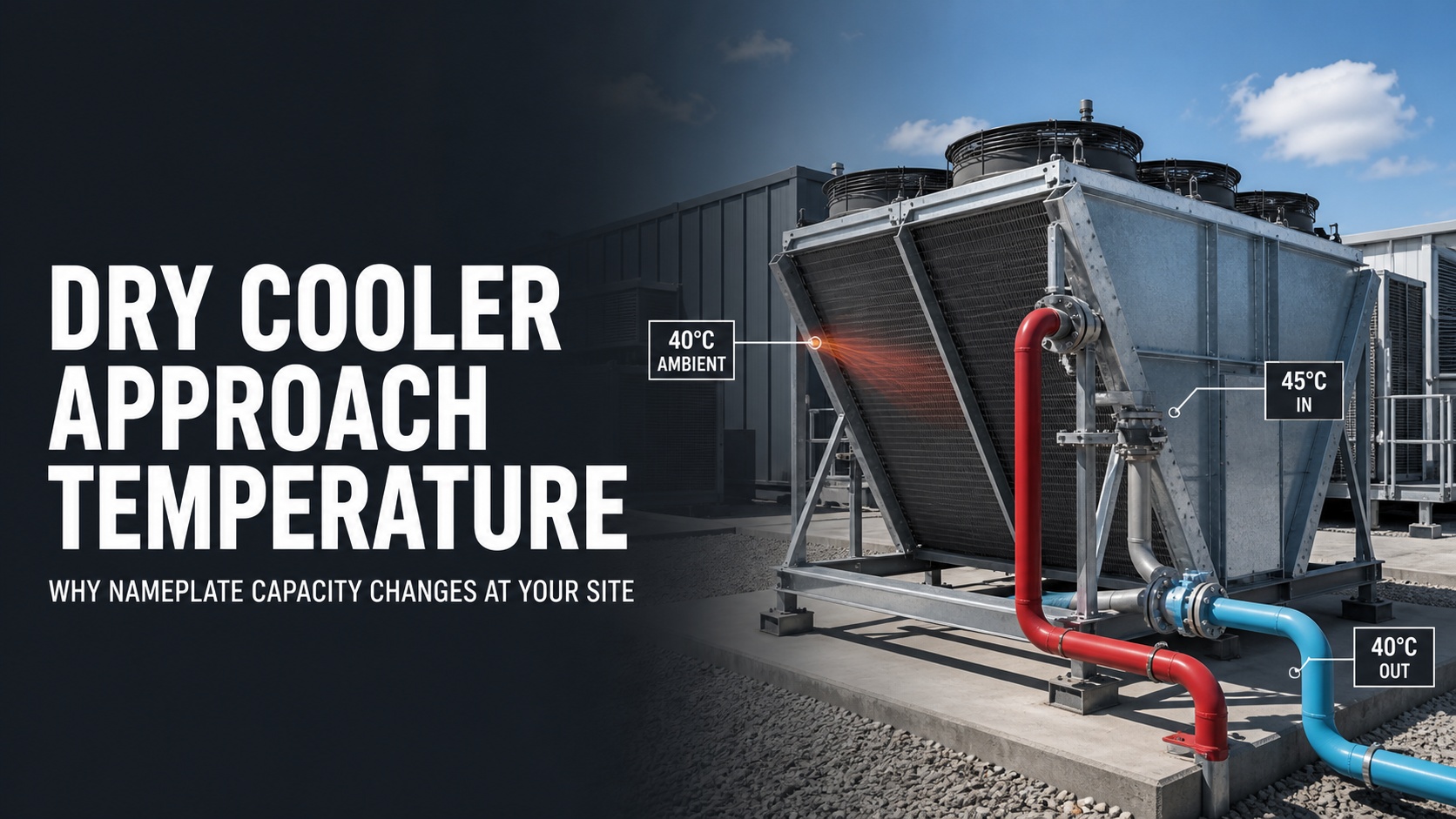
A dry cooler labeled “1 MW” is not a 1 MW machine under every operating condition.
That rating belongs to a specific combination of entering-air temperature, entering-fluid temperature, leaving-fluid temperature, fluid type, flow rate, fan speed, and altitude. Change any one of those variables, and the available heat rejection capacity changes with it.
This is why a dry cooler can appear correctly sized on a quotation while the coolant supply temperature continues to rise during summer operation. The equipment may not be defective. It may simply be operating at a much tighter temperature approach than the condition used to generate the catalog rating.
For data center buyers, the real question is not:
“How many kilowatts are printed on the nameplate?”
The better question is:
“How many kilowatts can this dry cooler reject at my actual design ambient temperature and required fluid temperatures?”
Nameplate Capacity Is an Operating Point, Not a Permanent Output
Dry-cooler capacity is always tied to test conditions.
Under the Eurovent Heat Exchanger certification program, one standard condition for dry coolers uses:
Entering air temperature: 25°C
Entering water temperature: 40°C
Leaving water temperature: 35°C
At this condition, the dry cooler has a 10 K approach between the leaving water and entering air:
35°C – 25°C = 10 K
It also has a 5 K fluid temperature range:
40°C – 35°C = 5 K
If a manufacturer rates a unit at this condition, the published capacity cannot be transferred directly to a project requiring 35°C leaving fluid when the outdoor air is already 35°C.
The temperature approach would be zero. A standard dry cooler operating only with ambient air cannot maintain fluid at the same temperature as the entering air while rejecting a meaningful continuous heat load.
The nameplate has not changed. The available site capacity has.
What Is Dry Cooler Approach Temperature?
For practical project discussions, dry cooler approach temperature can be defined as:
Approach Temperature = Leaving Fluid Temperature – Entering Air Dry-Bulb Temperature
For example:
Entering air: 30°C
Leaving fluid: 40°C
Approach: 10 K
A smaller approach means the dry cooler must push the leaving-fluid temperature closer to the outdoor-air temperature. That requires more coil surface, more airflow, higher fan power, or some form of adiabatic assistance.
A larger approach gives the dry cooler more temperature difference to work with. Heat transfer becomes easier, and a smaller unit may be capable of rejecting the same load.
Three temperature differences must not be confused:
Fluid range
Entering fluid temperature minus leaving fluid temperature.
Approach temperature
Leaving fluid temperature minus entering air temperature.
Entering temperature difference
Entering fluid temperature minus entering air temperature.
Some selection programs and suppliers use different terminology, including ETD or initial temperature difference. Therefore, every RFQ should show the actual temperatures instead of relying only on the word “approach.”
Pro Tip: Write all three temperatures directly in the RFQ: “45°C entering fluid, 40°C leaving fluid, 35°C entering air.” This prevents a supplier from interpreting the requested approach differently.
Why Summer Supply Temperature Keeps Rising
When the outdoor temperature rises, the dry cooler loses part of the temperature difference that drives heat transfer.
Consider a system selected at:
25°C entering air
40°C entering fluid
35°C leaving fluid
10 K approach
If the entering air rises to 35°C while the project still requires 35°C leaving fluid, the original 10 K approach disappears.
The fans may run at full speed. The pumps may show normal status. The dry cooler may still be clean. Yet the system cannot maintain the original leaving-fluid setpoint because the requested operating condition is no longer thermally realistic for a dry-only system.
The controls usually respond by allowing the fluid temperature to rise until a workable temperature difference returns. If the dry cooler still needs approximately a 10 K approach, a 35°C entering-air condition may require a leaving-fluid temperature closer to 45°C.
Whether that temperature is acceptable depends on the CDU, heat exchanger, secondary coolant loop, server manifolds, cold plates, and IT equipment limits.
This is why data center dry cooler sizing cannot be separated from the complete liquid-cooling architecture.
The CDU Adds Another Temperature Difference
In many AI data center systems, the dry cooler is installed on the primary side of a CDU. The server coolant remains isolated on the secondary side.
Heat must pass through several temperature layers:
The server transfers heat to the secondary coolant.
The secondary coolant transfers heat through the CDU heat exchanger.
The primary coolant carries the heat to the dry cooler.
The dry cooler rejects the heat to outdoor air.
Each heat-transfer stage needs a temperature difference.
If the server requires a specific secondary supply temperature, the primary fluid returning from the dry cooler normally needs to be cooler than the secondary supply temperature. The exact difference depends on the plate heat exchanger, flow rates, fouling condition, and control strategy.
As a result, a project cannot use the server coolant target as the dry-cooler leaving-fluid target without checking the complete temperature budget.
A system may lose temperature margin at three different points:
Dry cooler approach to ambient air
CDU heat-exchanger approach
Secondary-loop temperature rise through the racks
When these margins are omitted during procurement, the dry cooler often receives the blame even though the original system temperatures were incompatible.
Heat Load and Flow Rate Must Be Read Together
The basic liquid-side heat equation is:
Heat Duty = Mass Flow × Specific Heat × Fluid Temperature Range
For approximately 1 MW of heat rejection using water with a 5 K temperature range:
1,000 kW ÷ (4.18 kJ/kg·K × 5 K) ≈ 47.8 kg/s
That is approximately 172 m³/h of water flow.
If the project reduces the fluid range from 5 K to 3 K while keeping the same heat load, the required flow increases significantly. Larger pumps, pipes, valves, manifolds, and heat exchangers may then be required.
If glycol is added for freeze protection, the calculation changes again. A water-glycol mixture normally has different specific heat, density, viscosity, and pressure-drop characteristics compared with pure water.
Therefore, the supplier must know:
Glycol type
Glycol concentration
Design fluid temperature
Required flow rate
Maximum allowable pressure drop
Selecting the dry cooler with water data and later filling the system with a higher glycol concentration can reduce heat-transfer performance and increase pumping demand.
Pro Tip: Do not add a generic 20% capacity margin to a water-based catalog rating and assume glycol is covered. First rerate the unit using the actual glycol concentration and temperatures. Add the project margin afterward.
Seven Reasons Available Capacity Differs From the Catalog
1. Higher Design Ambient Temperature
Average summer temperature is not a sufficient design input.
The project needs a defined design ambient temperature based on location, operating expectations, and the number of hours the facility can tolerate above the selected condition.
A dry cooler selected for 35°C ambient will not automatically maintain the same leaving-fluid temperature at 40°C or 45°C ambient.
2. A Tighter Required Approach
Reducing the approach from 10 K to 5 K is not a minor adjustment. The coil must reject the same heat with less temperature difference.
This can require a larger coil, additional dry-cooler modules, higher fan speed, or adiabatic pre-cooling.
3. Incorrect Entering and Leaving Fluid Temperatures
A request stating only “1 MW dry cooler” is incomplete.
The same 1 MW heat load may require very different equipment at:
40°C entering and 35°C leaving
50°C entering and 45°C leaving
45°C entering and 40°C leaving
The fluid range may be identical, but the approach to ambient air is different.
4. Glycol Concentration
Glycol protects the system against freezing, but it changes fluid properties. Higher viscosity can increase pressure drop, while different thermal properties affect required flow and heat transfer.
The final concentration should be based on the project’s minimum temperature and freeze-protection strategy, not added after equipment selection.
5. Reduced Airflow
Available capacity falls when airflow through the coil is reduced by:
Dirty fins
Blocked intake areas
Incorrect unit spacing
Wind effects
Fan failure
Low fan-speed settings
Acoustic restrictions
Snow, leaves, or other debris
The performance sheet should state the fan operating point used for the capacity selection.
6. Altitude and Air Density
At higher elevations, air density decreases. A given fan volume does not carry the same mass of air as it would at sea level.
Projects at elevation should request altitude-corrected performance rather than relying on a standard sea-level selection.
7. Redundancy Requirements
A cooling plant may meet the design load with all units operating but fail the same load after one fan bank, pump, or dry-cooler module is unavailable.
True N+1 performance should be checked at the design ambient temperature and required fluid setpoint, not only by counting installed units.
Hot-Air Recirculation Is a Site Multiplier
Approach temperature must use the air temperature actually entering the coil.
A nearby weather station may report 38°C, while the dry cooler receives 42°C air because hot discharge air is returning to the intake. In that case, 42°C is the relevant temperature for capacity evaluation.
This is where approach-temperature design connects with our article on How Hot-Air Recirculation Reduces Cooling Capacity.
However, the two problems are not identical.
Approach temperature is a selection issue. Hot-air recirculation is a layout and airflow issue. A correctly selected dry cooler can still underperform when the installed airflow pattern raises the entering-air temperature above the design condition.
A Practical Capacity Example
Assume an AI facility needs to reject 1 MW continuously.
The original selection point is:
Design ambient: 25°C
Entering fluid: 40°C
Leaving fluid: 35°C
Approach: 10 K
Fluid range: 5 K
Now move the same unit to a hotter site:
Design ambient: 40°C
Required leaving fluid: 35°C
This condition asks a standard dry cooler to produce fluid 5 K below the entering-air temperature. Dry-only operation cannot achieve it.
There are five realistic options:
Raise the allowable primary-fluid temperature.
Increase the dry-cooler heat-transfer surface and airflow.
Use adiabatic pre-cooling during peak conditions.
Add a chiller or trim-cooling stage.
Reduce the IT load during extreme weather.
The correct option depends on server temperature limits, water availability, electricity cost, annual climate hours, capital cost, and acceptable derating risk.
“Add more fans” is not a complete engineering answer.
Correct Data Center Dry Cooler Sizing Workflow
Step 1: Define the Actual Heat Rejection Load
Confirm whether the stated capacity represents:
IT load
CDU load
Primary-loop heat
Total commissioned load
Future expansion capacity
Include pump heat and other loads that actually enter the liquid loop.
Step 2: Select the Design Ambient Condition
Use project-location climatic data rather than an annual average.
Also define what happens above the design condition:
Temporary higher fluid temperature
Adiabatic operation
Chiller assistance
IT derating
Reserved cooling capacity
Step 3: Establish the Full Temperature Budget
Define:
Server secondary supply and return temperatures
CDU heat-exchanger approach
Primary supply and return temperatures
Dry cooler leaving and entering fluid temperatures
Entering-air design temperature
Step 4: Confirm Fluid and Flow
Provide:
Water or glycol type
Glycol percentage
Design flow rate
Minimum and maximum flow
Allowable liquid-side pressure drop
Step 5: Request Performance at the Actual Operating Point
The selection sheet should show:
Heat rejection capacity
Entering and leaving fluid temperatures
Entering-air temperature
Fluid concentration
Flow rate
Pressure drop
Fan quantity and speed
Fan power
Sound data
Altitude correction
Fouling or safety allowance
Step 6: Verify Degraded Operation
Repeat the selection with:
One dry-cooler module unavailable
One pump unavailable
One fan bank unavailable
Partially loaded coils
Maximum expected ambient temperature
Pro Tip: Ask for two selections, not one: the normal design point and the maximum summer or degraded-operation point. The second sheet often reveals more procurement risk than the headline capacity.
What Buyers Should Include in a Dry Cooler RFQ
Before requesting a quotation, send the supplier:
Project location and elevation
Maximum design dry-bulb temperature
Required heat rejection capacity
Entering fluid temperature
Leaving fluid temperature
Fluid type and glycol concentration
Required flow rate
Maximum allowable pressure drop
Available voltage and frequency
Noise limit
Required fan-control method
Redundancy requirement
Air-quality and corrosion conditions
Available installation footprint
Required maintenance clearance
Dry-only or adiabatic operating preference
Future expansion plan
Without these inputs, a quotation may provide a model number, but it cannot provide reliable site performance.
The ROI Risk Is Not Oversizing. It Is Oversizing the Wrong Condition
A larger dry cooler increases capital cost, footprint, shipping cost, and sometimes fan energy. Yet undersizing can create a much larger financial problem through:
Higher coolant temperature
GPU or ASIC derating
Emergency IT-load reduction
Additional rental cooling
Retrofit piping and electrical work
Accelerated fan operation
Lost compute availability
The correct ROI calculation should compare systems at the same site operating point.
Do not compare one supplier’s 1 MW rating at 25°C ambient with another supplier’s 1 MW selection at 40°C ambient. Those are different thermal duties even though the headline number is identical.
First normalize the temperature, fluid, flow, altitude, fan speed, and redundancy conditions. Then compare CAPEX, fan power, water use, footprint, maintenance, and expected availability.
Final Verdict
A dry cooler nameplate is a reference point, not a site guarantee.
The available heat rejection capacity depends on the temperature difference between the process fluid and the air entering the coil. As summer ambient temperature rises, that difference shrinks. If the required leaving-fluid temperature remains unchanged, the dry cooler must work at a tighter approach and its available capacity changes.
For AI data centers and liquid-cooled mining projects, the correct sequence is:
Define the heat load. Set the design ambient. Build the temperature budget. Confirm fluid and flow. Then select the dry cooler.
Buy the operating point, not the nameplate.
Explore the ACT-Boxes Data Center Dry Cooler or contact our engineering team to review your heat load, site climate, coolant temperatures, flow rate, and redundancy requirements.
FAQ
What is a typical dry cooler approach temperature?
There is no universal approach for every project. A 10 K approach is easier to achieve than a 5 K approach, but the correct value depends on the required fluid temperature, design ambient condition, coil size, airflow, energy target, and available footprint.
Can a dry cooler cool water below outdoor temperature?
A standard dry cooler cannot continuously cool fluid below the dry-bulb temperature of the entering air. Adiabatic pre-cooling can lower the entering-air temperature, while a chiller can provide fluid temperatures below ambient.
Why does dry cooler outlet temperature rise in summer?
As ambient temperature increases, the temperature difference available for heat transfer decreases. The fluid temperature then rises until the dry cooler regains enough temperature difference to reject the applied load.
How much spare dry cooler capacity should a project include?
There is no reliable universal percentage. First select the equipment at the actual design ambient, fluid temperatures, glycol concentration, flow, and altitude. Then add capacity for fouling, aging, expansion, extreme weather, and the required redundancy strategy.
What is the most important information for dry cooler selection?
The minimum inputs are heat load, design entering-air temperature, entering and leaving fluid temperatures, fluid type, glycol concentration, flow rate, altitude, allowable pressure drop, fan requirements, and redundancy level.